

Article By: Wayne at Wicked Willy’s Choppers
Here in part seven of our trike build, we are going to start our foot controls. I will be building a custom foot clutch using our own forward controls. This will take two parts because I will show you how to measure and make your own cable out of a stock cable and sleeve.

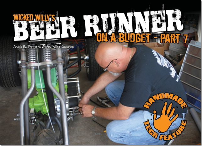
First thing I do is bolt the primary plate to the motor and tranny. We will be using an open belt primary with an outboard bearing support. It’s important to mock- up the motor, tranny, and primary so that we can check for line up and since we will be making a clutch cable, we’ll need everything in place to get our length.

Once I have my plate mounted, I install the motor and tranny pulley with the belt. I want to make sure my belt does not hit my cable when I install it because I will be going under the primary with the cable and it will be a close fit. Shown is the primary mounted with the outboard bearing plate. This is as far as I need to take it at this time. This should be enough for mock-up.


Just like our last build, I went to see my friend at Mud Pro and had him plasma cam a couple of parts to make my controls from. Here is the mounting plate and peddle arm for my forward controls.

I then machined a barrel to weld to my pedal arm so it can hold a bronze bushing and it’s wide enough to give it some support. My pedal arm is fish mouthed to fit the barrel. Now I am ready to bolt it into a welding jig I made to fix my controls with.

You can see my pedal arm bolted into my jig. This will keep things square and lined up so my controls will also line up.

First step in welding and keeping it straight is to take weld on both sides of the part to keep from moving with the heat from the welding.

While it’s bolted in the jig, I TIG weld my parts together. I also leave the parts in the jig till they are completely cooled so they don’t pull from the heat, this way my pedals are nice and straight.

This is my part with the bushing installed correctly. I am now ready to start building my forward controls.

Since I am building a custom foot clutch, I can go ahead and mount my brake side. This way I can measure the other side to get the right height from the toe peg to the ground. I do this because the brake side is already made up.

Here is the left side mounted. You can see that my toe peg on my clutch side is the same height as the toe peg on the brake side. I use a small piece of shim to lock down my pedal while I fab my clutch.

Shown here is the threaded end out of a stock clutch cable. I will use the threaded part of the cable sleeve for the adjuster for my clutch cable. Now I will fab a part for my control to hold my adjuster.

Here is the part I cut out to hold my adjuster. Notice the notch I cut out in the side. This will be so I can get my cable end in when I mount the finished cable.

This is my adjuster part tack welded to my forward control mount. I think you can see the idea I have going on here.

Next time in part eight, we will finish making our cable and hooking up our foot clutch and you will get the full picture. If you have any questions about this segment feel free to call me at the shop 828-303-0422 or e-mail me through the Web site www.wickedwillychoppers. com.
If you would like to purchase this issue, click here to be linked to our back issues page.


