

Frame Jig From Scratch At Flat Broke Chops And Rods
Article and Photos by: Chris Callen – Editor In Chief
Originally Published In The April 2015 Issue Of Cycle Source Magazine
This month Cycle Source moved the Source Garage into its new home at Flat Broke Chops & Rods. The first order of business is to get ready for the upcoming winter projects. Since quite a few of the projects involve the manipulation of a frame in one manner or another, we needed a frame table. With the help of our brother Flip, we got the use of his table but it was just a reference table with only the front upright and neck fixture. After a few hours of looking around and asking questions of some builders I know, we decided to just build our own frame jig. The plan would be to build a modular jig that will allow us to work on sportsters and big twins alike. That said, this article is one example of how to go about this task. While we make no warrant that we are experts and you may find a better way, one thing we can tell you is if you intend to work on motorcycle frames (hard tailing, raking or the like) you should be able to build your own jig. By doing this you learn so much about the frames and what you need to pay attention too in their manipulation. We’re a bunch of knuckleheads that are always down for learning something new so here goes.
Here’s our loaner table the way we got it from Flip. The upright for it bolts on and it has leveling bolts on the feet.

After making some loose plans we headed off to our local steel yard. Like I said in our “Custom Bike Building Basics” book, it’s a must to have a solid relationship with a steel supplier. Metco in Vandergrift PA always takes care of us and even cuts our material to size

Back at the shop we start off by getting the table into a spot, located the feet on that spot with spray paint and leveled it as it stood. That way we knew we were starting off square.

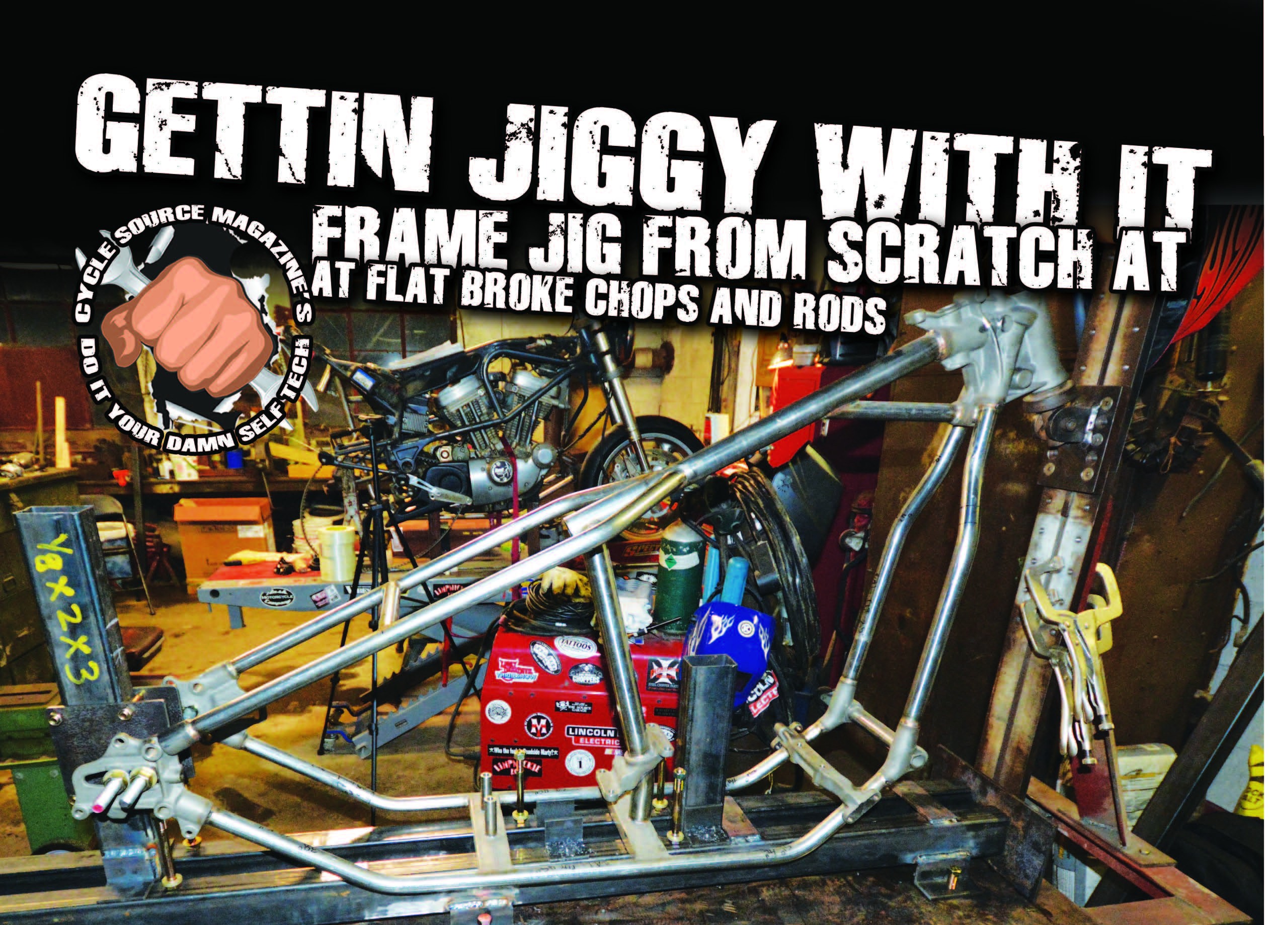
What you see here is our rough mock up. We have two lengths of 2×3 quarter inch box steel that are 7 feet long and will serve as our main rails. The shorter lengths of the same material will be our uprights that will slide between our main rails to accommodate different length frames.

Our hardware selection is readily available at any of the big box or local hardware stores. It might be overkill but we choose to use grade 8 hardware. There are various sizes and lengths of bolts, spacers and all thread that will be identified as we go through the construction.

To start off we cut a number of 3-inch and 2-inch sections of the angle iron both for feet for the jig and side tabs for the uprights.

We establish a centerline with a laser line level and place our main rails parallel to the centerline. The rails are elevated 1.5” off the table to allow us to secure the modular fixtures from the bottom.

We place three of our three-inch angles along the sides of both main rails. These are drilled out first so later the frame jig can be bolted to the table.

The rails are secured in place as we weld the cross supports and feet to the main rails. Everything is checked and re-checked for level and square.

Here you can see the clearance we established on the underside of the main rails of the jig.

With the main base complete but still not bolted down we start on the tail section. Using a two foot section of the 2×3 box tubing, we slide it down between the main rails until it is flush with the bottom of the rails. Once we square and level the upright, the 2×2 angles are welded to both sides. These will serve as anchors to the main rails once we drill them (and the rails) to accept hardware.

Next up is the sliding fixture that will locate our axle plates on the tail section. We start with our 6” wide pieces of quarter inch steel. We cut two 9” lengths and map out the plan for the drill press.

We take all the steel we cut to the belt sander to de-burr the edges since most of this will constantly be in contact with hands. Sharp edges on any tool suck!

Here you can see the plates drilled out for both the 3/8 pinch bolts that will lock the plates to the upright and the 5/8 all thread that will locate the axle sliders.

The tail section upright is complete here, all but the attachment to the main rails. That will come later once we decided what we’ll need from it. For now we’re ready to load a frame onto the table move on.

We take the 5/8 all thread and cut it into two 14 inch sections. The reason there are two is so we can insure level and square on both the vertical and horizontal planes. That way the axle will slide level along the length of the slider and not raise, lower or bind. We use some steel spacers to slide over the all thread so not only the axle plates are spaced from the center line but also so they rest on spacers and not the thread.

Once the frame is locked into our neck upright and tail section we pull out the laser again and make sure one more time everything is centered, level, and square.

With that last check we locate, drill and tap our table top to accept the 17/32 bolts that will attach the jig to the table. Tip for this is to start small when drilling and go up in steps.

At this point we’re pretty happy at how the jig is shaping up. We start to plan out our motor locators but notice that we may have forgotten an important part of this design; frame rail lock downs. With new frame construction in mind for down the road, we want to be able to lock the frame in as many known positions as we can.

We also realize that the neck fixture that came with the table does not fit the smaller neck size of an Ironhead Sportster. Both of these issues would be more easily dealt with if we had our machines set up at Flat Broke, but we are not quite there yet.

So for this, or any time we get in a jam, we head off for some time with the boys at Ed Fish Machine. One of the only “Manual Only” machine shops you’ll find these days, meaning there isn’t one piece of CNC machinery in their shop. These guys are incredibly talented and constantly go to bat for us.

After some quick drawings and measurements they break up and split the job into two tasks. Curt starts on turning down the neck stem.

He also made us some steel cones that will locate a variety of frames from British and Asian through Sportster and Big Twins.

At the same time Carl cuts us four 2×2 blocks of steel that will be used to make our frame rail lock downs.

Doug then takes the blocks to the milling machine to begin drilling the half inch holes for the locking hardware that will clamp the two halves of our frame rail clamps together.

Then with several passes for each grove he machines v grooves in at 4 inches on center for Sportsters and 8 and 15/16 on center for Big Twins. The fact that they are v grooves will allow for stock and oversized tubing.

Here’s the crew from Ed Fish Machine. Again, and also from the book “Custom Bike Building Basics” having a relationship with a solid and capable machine shop is crucial for this type of work. Even if you have your own machines, you can always use some help from a cast that does it day in and day out. Thanks again.

Here is one completed frame rail lock down. You can see that the pieces that lock the frame into position will be held in place by a one inch piece of steel that’s attached from the center by a socket head bolt.

Switching gears back at Flat Broke we have loaded our ’72 Ironhead frame into the jig. We have a Led Sled hard tail kit to do on this thing next so we are going to continue in the Sportster direction first. As it is right now we have about $350 dollars into the construction of this jig and a good weekend of work on it. Once it’s done this will be a tool we can use forever in the shop and make small modifications that will adapt it to anything we need to do with it. When we come back next month we’re gonna fabricate our motor mount locators for both the sportster and big twins and hopefully get this hard tail done. You can see a complete video of this project, up to the point that it sits here, on our web site at www. cyclesource.com If you would like a set of plans on a jig simmilar to this one it can be downloaded from the VooDoo Vintage website.
This post is sponsored by:


