


Article By: Paul Wideman at Bare Knuckle Choppers – www.bareknucklechoppers.com
Originally Published In The September 2012 Issue Of Cycle Source Magazine
Between the guys at Twisted, Big Will from Faith Forgotten, and myself, there have been plenty of gas tank articles over the last few years in Cycle Source. Looking back on this, I realized that it had been ages since we did a tech article on a gas tank that the home builder can do, with simple tools that most any home builder might have. All of this stuff can be done right in your garage, and while you may not have the exact tools that we do, easy substitutes are likely lying around right in your tool box. Check it out…
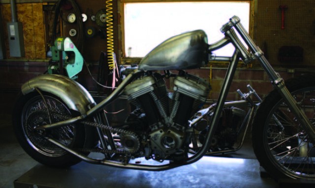
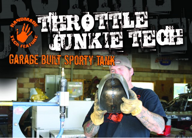
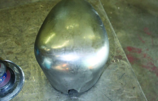
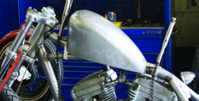
This little Buell chop looks like a Sporty style tank will fit it just right. Well, the King Sporty we picked up at the swaps looks Article By: Paul Wideman at Bare Knuckle Choppers www.bareknucklechoppers.com okay, but definitely not what we want without some major mods.
Shannon sets about the makeover by removing the filler bung and the bottom.
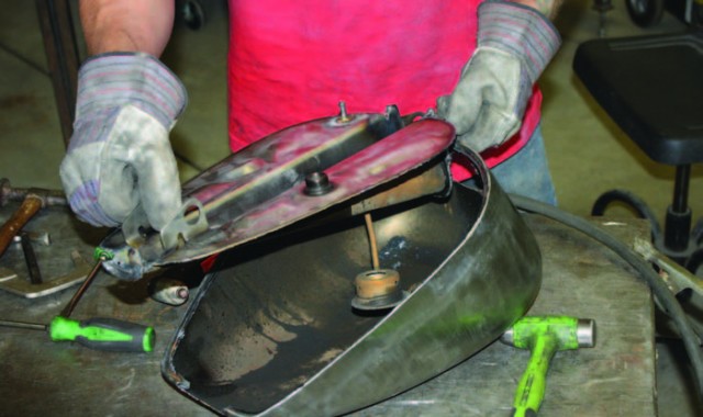
We saved the filler bung and the entire bottom. We will probably only use the petcock bung, but the filler bung is handy to keep on the shelf.
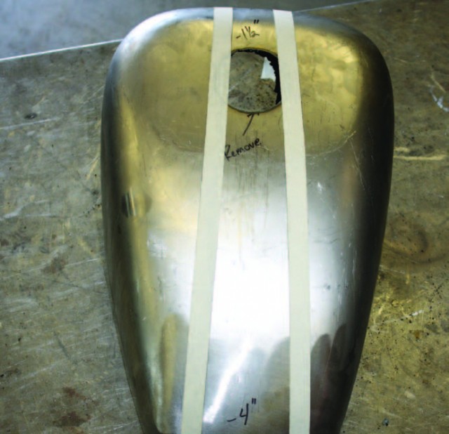
Using a couple quick measurements and some masking tape, we lay out our plan.
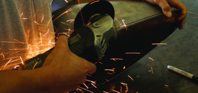
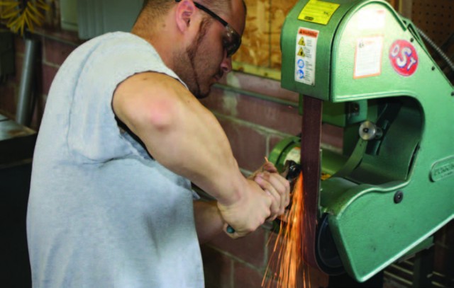
After some cutoff wheel work, Shannon has lost a good bit of weight from the tank…
…but not enough. Using some simple c-clamps we adjust the tank halves to better suit the look we are after.
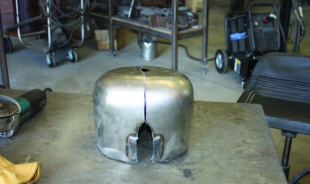
Shannon lays out a new centerline with marker, and he then cuts both sides on the mark.
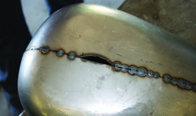
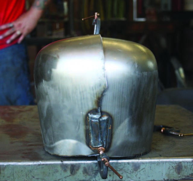
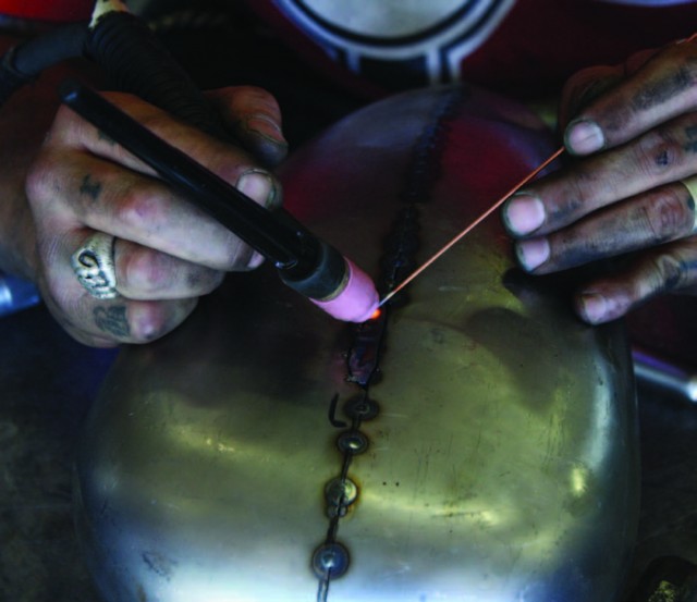
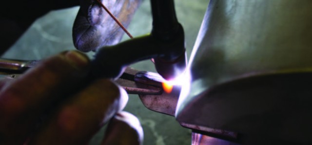
After a lot of fitting and tacking, we have the two halves together.
Once we grinded the edges where the filler bung once was, Shannon makes a filler piece. He used some of the material he cut from the center for the filler piece. This assures the same material thickness
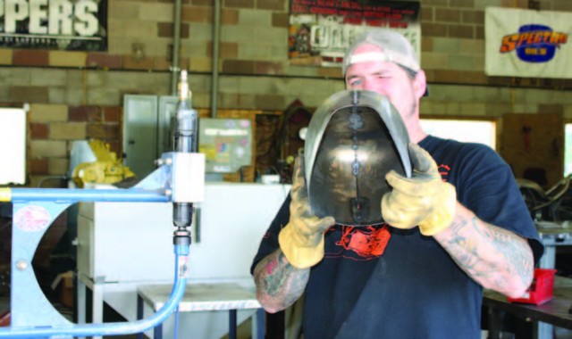
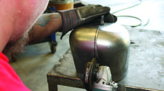
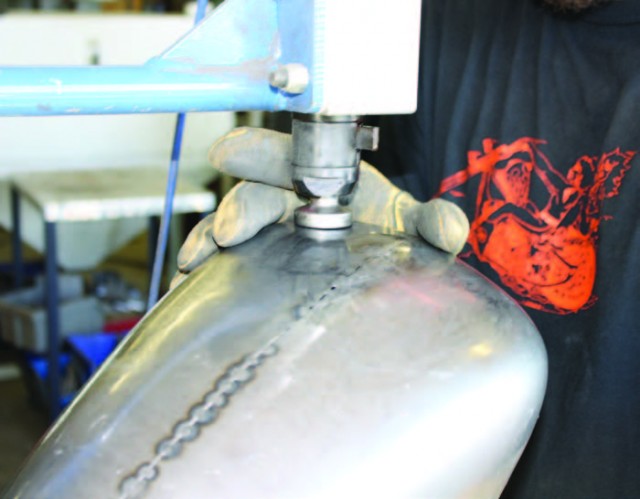
I took the tank to the planishing hammer and qualified the weld area. While I used the planishing hammer, you can also achieve the same effect with body hammers and dollies.
I also removed the flat spot from the old cap area. Nothing looks worse than a great tank with the old flat spot.
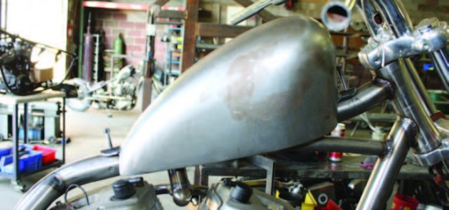
Awww…Pretty.
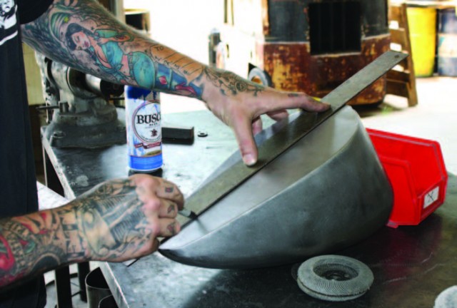
Using a piece of 1/4” plate for a guide, Eric traces a straight, level line all the way around the bottom of the tank.
Eric now trims the sides for the bottom to mate to, and in the process caught his shirt on fire.
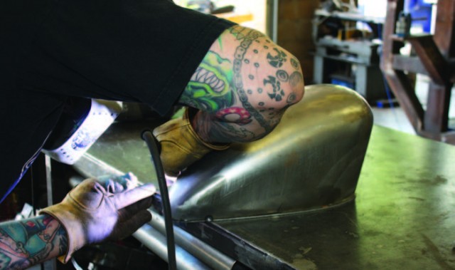
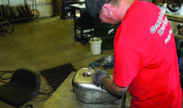
While Eric is working on the petcock bung, I welded the bottom to the sides. Note that we have not made any provision for the tunnel thus far.
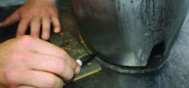
Eric removed the petcock bung from the old bottom, and ground away excess on the belt grinder. A quick pass or two with the lathe and all of the old weld and base metal is gone. This is far quicker and easier than making your own, or paying a machinist.
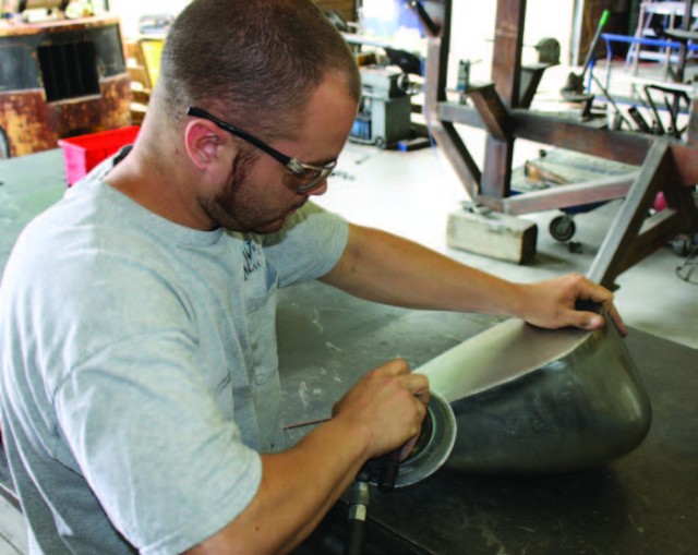
After I welded the bottom up, Eric used a flap wheel, then a couple different grit discs on a 2” angle grinder, then the DA to slick up the bottom; still no tunnel.
To lay out the tunnel, we simply found the center of the tank, and laid out a centerline with a straight edge.
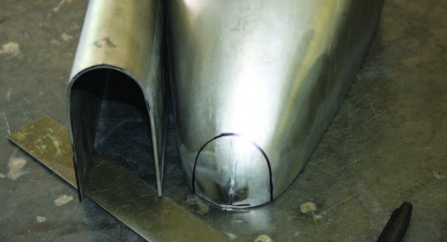
We measured the sides of our tunnel, and then transferred the lines across the length of the bottom. Using the tunnel as a pattern, we traced the shape onto the rear and front of the tank. We then cut out the front, bottom, and rear.
Using a barrel sander, Eric worked the edges down for a tight, snug fit.
Next, we traced the tank shell onto the tunnel. We will leave a long 1 1/2” wide strip to the front and rear for the mounts.
After cutting away the unneeded tunnel material, we used a couple chain clamps to align the tank on the tunnel. Clamped in place, the tunnel is ready for tacking and welding.
We welded and finished the tank bottom and tunnel. We then rounded off the tank mounts, and made two more tabs. Here, Shannon is welding the second tab to the bottom of the tab that is part of the tunnel. This will add strength. After laying out the mounts on the backbone, Shannon tacks them in place. You can read more about this in Daniel’s column this month.
We found the highest place on the tank, and the centerline of the tank shell, and Shannon uses a hole saw to make room for the new filler bung. We keep a long bolt around to help hold and align our filler bungs. After final welding and pressure testing, our new tank is done. While we did use a few tools you may not have in your home garage, this entire project can be done quite easily with common tools. You can substitute the plasma cutter with a cutoff wheel, the planishing hammer with body tools, and the lathe with a dremel tool or small grinder. This project took basically a day, and we only had the price of the tank purchase invested, plus the small amount of consumables. While we used one of our gas caps, you could have used the original filler bung. You could easily build this tank in your garage in a weekend for less than $150. Until next, FTW!


